
 Haoru UWB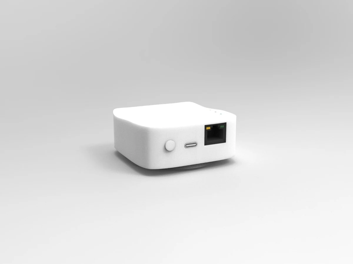
Plan UWB anchor placement, NLOS checks and update-rate tests. Understand ranging error versus positioning accuracy before deploying an indoor RTLS.
UWB indoor positioning performance depends on the complete installation: anchors, tags, radio settings, the positioning algorithm and the environment. A module's maximum line-of-sight range or ranging accuracy is useful for selection, but neither number on its own describes the position error your application will see on site.
Ranging accuracy and positioning accuracy are different
Ranging error compares a measured distance with a reference distance between devices. Positioning error compares the estimated coordinates with a surveyed or independently measured reference position. Several good ranges can still produce a poor position if the anchor geometry is unsuitable. Vertical accuracy also needs separate evaluation from horizontal accuracy.
When comparing results, state whether the value is a mean error, an RMS error, a percentile or a maximum observed error. Include the test area, tag height and orientation, motion, obstruction conditions and firmware. Do not combine different error definitions into a single promise of centimetre-level accuracy everywhere.
Place anchors around the working area
Start with the layout and coordinate setup in the applicable system manual. Spread anchors around the area where tags will actually operate and avoid treating a row of anchors as equivalent to anchors surrounding the workspace. Survey anchor coordinates consistently and check axis directions, units and mounting heights in the host software.
For 3D tracking, assess vertical geometry and height error explicitly. A flat anchor arrangement and a software 3D display do not by themselves establish useful height measurement. Evaluate boundaries, entrances and transitions between covered areas, not only a convenient point near the centre.
Check NLOS, metal and the installed tag position
Non-line-of-sight (NLOS) paths and reflections can bias measurements. Metal machinery, racks, changing loads and the human body can alter the available radio paths as the tag moves. Test with the tag in its intended mounting position and with representative objects and people present.
Keep antenna placement consistent with the module manual. Compare open-path measurements with the same route under expected obstructions, and record missing or rejected measurements as well as accepted positions. This helps distinguish an installation problem from an interface, calibration or configuration problem. Filtering may make output smoother without removing the underlying bias.
Tag count, update rate and latency
Wireless data rate, per-tag update rate and end-to-end latency are different quantities. A 6.8 Mbps radio setting is not a 6.8 million-position-per-second output. A maximum update-rate specification must be read with the operating mode and configured tag capacity.
For example, the ULM1 manual describes a 10 ms single-tag cycle at 6.8 Mbps, but a 28 ms slot per configured tag at 110 kbps, giving a 112 ms cycle for four tag slots. The ULM3 manual describes a 12 ms slot and a 96 ms cycle for eight configured tag slots at 850 kbps. These are model-specific scheduling examples, not a universal performance figure for all Haoru products. Reserved slots can remain part of the cycle when a tag is absent. Network transfer, host processing and filtering add to application latency.
Plan the data path as carefully as the radio layout
For IGA Ethernet anchors, verify PoE, IP addressing, destination host and UDP port, then configure the surveyed anchor coordinates in the positioning software. JSON and mc firmware formats require the corresponding parser. Check sequence information and missing updates so an old position is not mistaken for a new observation. Configure the required network access rather than disabling the host's firewall indiscriminately.
A practical site acceptance record
- Define the required horizontal and, if applicable, vertical error with a consistent reference method.
- Test static points and representative moving routes, including coverage boundaries and expected obstructions.
- Record the firmware, radio settings, anchor coordinates, tag count and per-tag output interval.
- Measure application latency, missing updates and recovery after communication interruptions.
- Repeat with the expected operating load before accepting the deployment.
Use TWR, TDoA and PDoA selection to choose the measurement approach, then consult the IGA01-EP, ULM1, ULM3 or HR-RTLS4 documentation for the actual hardware. Share your site plan and acceptance requirements through the project enquiry page.