
 Haoru UWB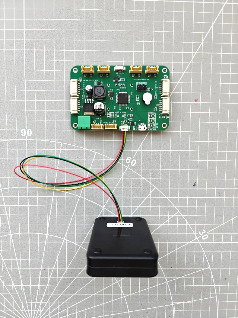
Learn how a UWB following kit connects tags, PDoA anchors, a controller and motor drivers. Plan chassis integration, obstacle sensing and commissioning.
A UWB robot following kit lets a compatible mobile platform follow a person carrying a tag. The UWB subsystem provides relative distance and direction; the vehicle controller turns those measurements into motion commands. Choosing the correct tag and anchor is only one part of integrating a reliable following cart.
The main components and their roles
- Carried tag: identifies the person or target to follow. Depending on the selected kit, this can be a wristband tag or a remote-control tag.
- Vehicle-mounted PDoA anchors: measure the target relative to the vehicle. The referenced follow_auto03 installation guide shows a front main anchor and a rear secondary anchor; the exact arrangement follows the supplied kit revision.
- Following controller: receives the UWB measurements and applies the selected following, steering and operating-mode behavior.
- Motor driver and motors: convert control commands into wheel motion. The driver, motor wiring and supply must match the actual chassis.
- Obstacle sensors: provide separate information about nearby objects. The installation guide describes ultrasonic options; other current configurations may use additional sensors.
- Power and wiring: supply the controller, sensing equipment and drive system with the required voltages and current capacity.
Adding following to an existing robot or cart
There are two different integration starting points. If your robot already has a motion controller, you may need the UWB ranging/angle subsystem and its documented data interface. If you are converting a motorized cart, a more complete kit can include the following controller, motor drive and selected obstacle sensors. Confirm the delivered configuration before designing the wiring harness or enclosure.
The ULM3-PDOA manual describes USB-to-serial and TTL UART output. A host controller can read the documented target, coordinate, distance and angle fields. Check field units and the exact firmware format before writing a parser. A measurement interface is not automatically a motor command interface: the receiving software must decide how to translate target measurements into the behavior of its own chassis.
Mechanical and electrical details to resolve first
Keep the antenna faces oriented as specified and assess whether the chassis, load or operator blocks the radio path. Check the coverage during turns as well as straight-line motion. A single PDoA module's angular field of view should not be presented as full-vehicle omnidirectional coverage.
For electrical integration, confirm supply voltage, motor type, driver command interface, connector pinout and signal-level compatibility. The referenced installation guide contains a 24 V configuration; that does not make every kit or vehicle a 24 V assembly. Use the wiring instructions for the configuration being delivered, including common-ground and power-distribution requirements where specified.
Commissioning a following system
Begin with stationary communication checks. Verify tag identity, range and angle output, anchor orientation and the controller's operating mode. Then check wheel direction and steering with controlled low-speed tests before adding the intended payload. Record behavior during starts, stops, turns and loss of the tag signal.
Test obstacle response in each operating mode. UWB target following does not itself detect every obstacle, and obstacle sensing is not the same as autonomous route planning. The referenced follow_auto03 guide states that obstacle avoidance is unavailable in its remote-control mode. Confirm the behavior of your supplied version and validate stopping and recovery on the completed vehicle; do not transfer a function demonstrated in one mode to all modes.
Information needed for kit selection
Send the chassis dimensions, payload, wheel arrangement, motor/driver details, supply voltage, desired following distance and speed, mounting positions and operating environment. Also identify whether you need raw measurements, an integrated controller or a complete vehicle. This lets the team check the integration boundary before selecting components.
See the UWB omnidirectional following kit, following development vehicle and ULM3-PDOA module. For application examples, read UWB kits for tool carts and mobile platforms. The product pages link the installation and module manuals; language labels identify documents that are currently available only in Chinese.